Tools & Automation
Automation at Sustainer Homes
A suite of automated design tools for a modular timber housing system — reducing week-long tasks to hours, and drawing CNC files to a 0.01 mm tolerance.
- Year
- 2017–2019
- Role
- R&D Designer & System Developer
- Office
- Sustainer Homes
- Domain
- Architecture · System Development
Meta-architecture
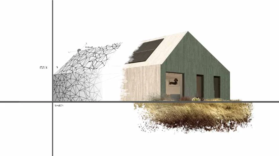
“The architect's focus should be on the client and the design. That's why our system takes care of the rest.” — Sol van Kempen, founder of Sustainer Homes. That sentence is why I joined the R&D department: automation in design and production is worth the effort whether it buys time or buys quality, and every repetitive task removed is energy returned to the part of the work that actually needs a designer.
I call this work meta-architecture. You stop solving one project and start solving the pattern behind all of them — every future house that will be built on the same system. It asks for a working knowledge of the software, the mechanics and logistics of the modular system, and the design patterns underneath both function and aesthetics, while deliberately leaving room for expression rather than closing it down.
The first job was not writing anything. It was walking the workflow end to end and finding where the hours actually went, so that each intervention paid for itself instead of automating something nobody was struggling with.
V5 — the software that draws the drawings
Alongside the fifth iteration of the Sustainer Homes modular system, I was part of the core team building a highly automated design tool for it. It produces the full permit set, the budget calculation, and the legal documents in hours, where the same package used to take a week or more.
My role sat on the seam between the design team and the programmers — translating what architects actually need into something buildable in code, and back again. It is tempting to leave this to developers alone, but the software is a tool for architects; most commercial tools fail precisely because nobody with the architect's perspective was in the room while they were built.
The CNC generator
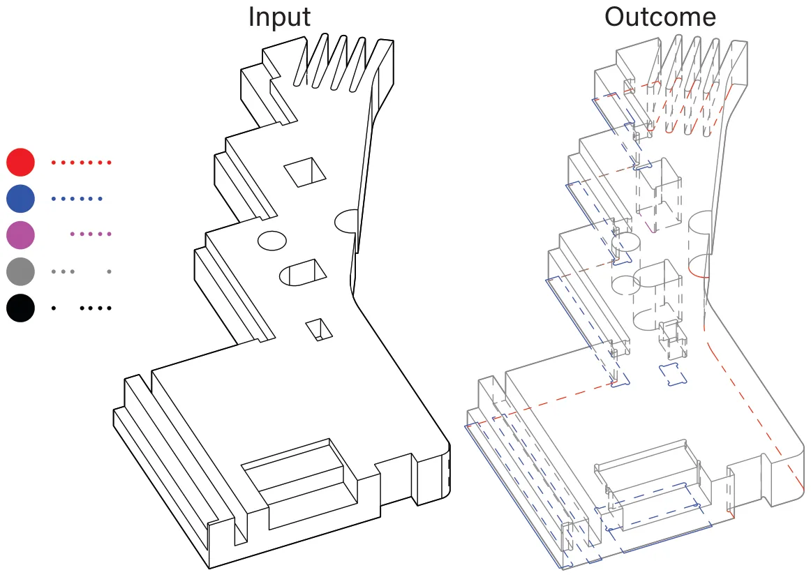
Preparing designed elements for the robotic CNC machine is the most time-consuming and least forgiving task in the R&D process. The drawings are long and intricate, and the robot's tolerance leaves a margin of deviation as small as 0.01 mm. A single inclined roof type can contain up to 128 unique elements, each needing its own drawing — and during prototyping each one gets redrawn again and again.
So I wrote a script that generates those CNC drawings automatically, in the exact style and format the machine expects. It took a long time to build once, and it has saved that time back on every project since.
Floor heating, recognised and routed
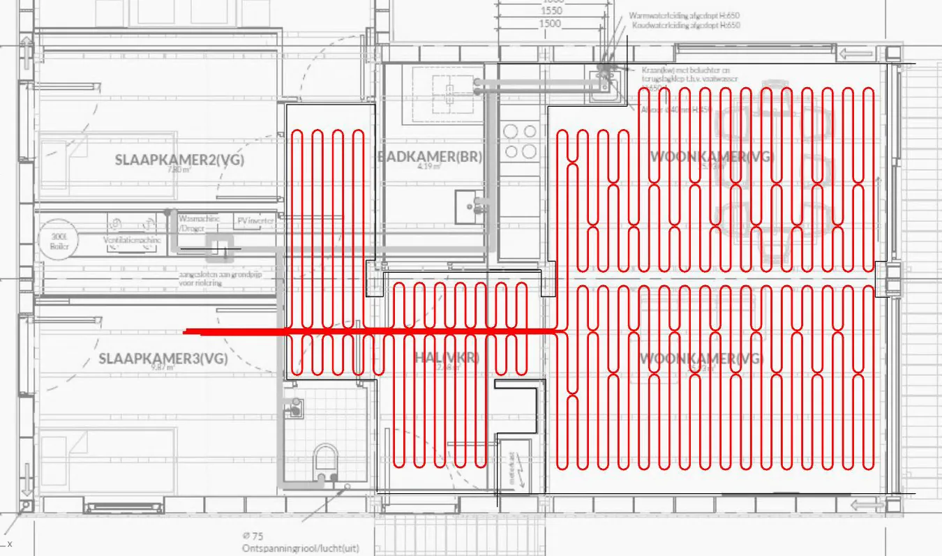
A second automation: a script that reads a space and lays out its floor-heating plan on its own, accounting for the cutting direction the structure demands, the total length of each pipe group, and the density needed per room.
It reaches an optimal loop layout in seconds and removes a slow, error-prone drafting job from both the design phase and the build.
Milled into the floor, not clipped onto it
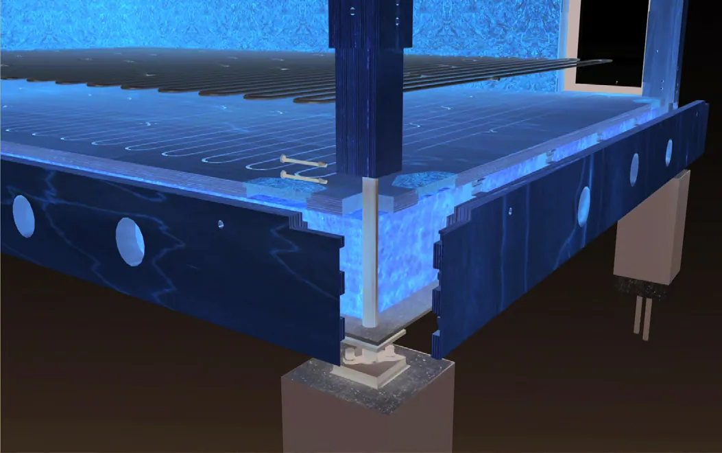
The pipes are milled directly into the floor elements underneath the finish layer, so the usual plastic support rails disappear entirely. Less material, fewer components on site, and a faster installation — which is only possible because the routing is generated from the same model the floor is cut from.
Behind the curtain
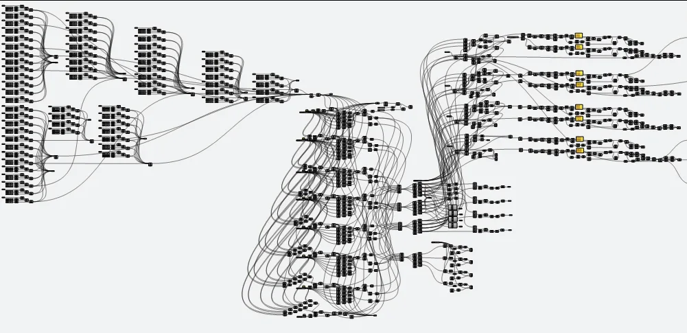
Everything runs inside Grasshopper with a heavy layer of custom Python. The scripts were written modularly from the start so components could be lifted from one task into the next instead of rebuilt — which is what made them maintainable once several people depended on them daily.
Next project
Boom Generative Tool